TR / EN
Logo
TUNÇMAKSAN
Worm Gear
PRODUCT INFO

Worm Gear

A worm gear set consists of a screw-like worm meshing with a toothed worm wheel. The geometry allows very high speed-reduction ratios in a single stage and provides self-locking capability — motion can only travel from the worm to the wheel, never the reverse.
CAPACITY
Ø 10 — 3100 mm
MODULE/STANDARD
Mn 0.5 — 25.4
TYPE
DIN / ISO / AGMA
EVALUATION

Worm Gear advantages and important considerations

Advantages

  • Compact design with low noise can reach very high reduction ratios. Can transmit much higher torque than other gear types.
  • Has a self-locking feature — motion travels only from the worm to the wheel. Advantageous for cranes and lifting equipment.
  • Good mesh performance with smooth and quiet operation.

Important Considerations

  • Efficiency is lower than other gear types. High friction losses, heat generation, and lubrication requirements.
  • Expensive to manufacture — requires special materials (e.g. phosphor bronze).
  • Low power transmission capacity, cannot operate at high speeds.
MANUFACTURING PROCESS

Worm Gear how is it manufactured?

01 / METHOD

Profile Design

Module, number of teeth, pressure angle, profile shift, center distance, speed ratio and power transmission are calculated based on ISO or AGMA standards.

02 / METHOD

Blank Cutting

Turning, milling, forging or casting forms the blank.

03 / METHOD

Tooth Generation

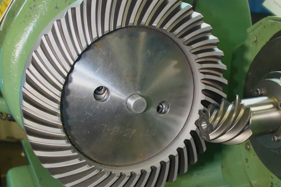
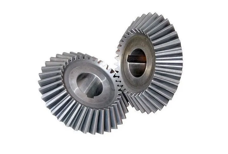
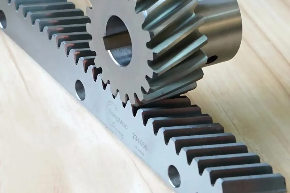
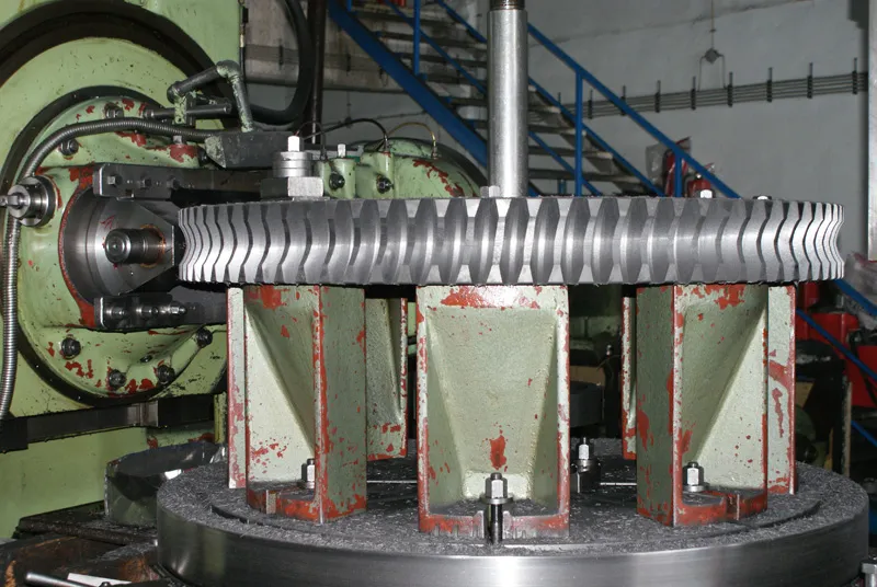
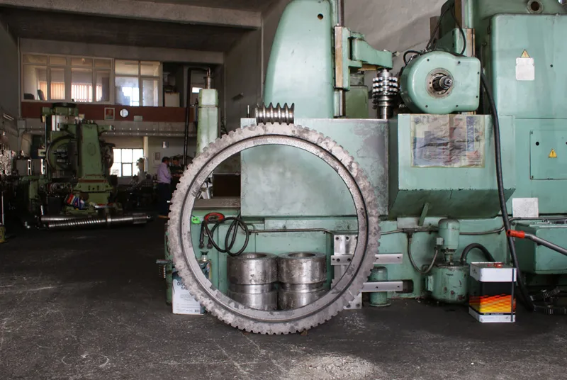
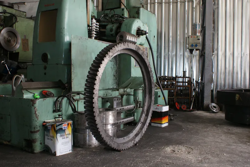
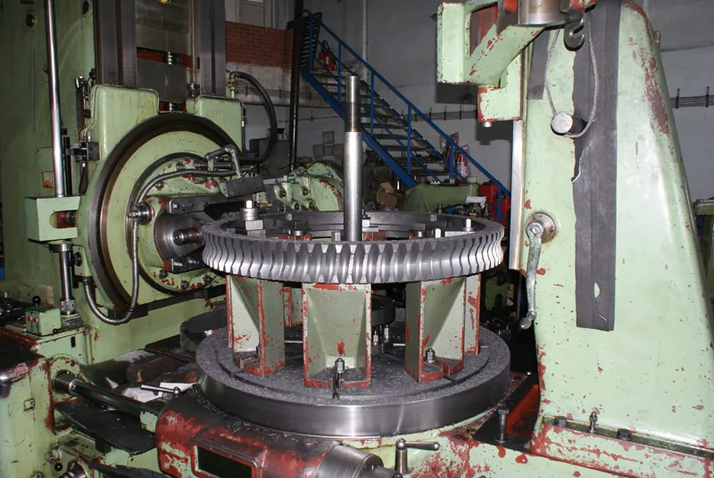
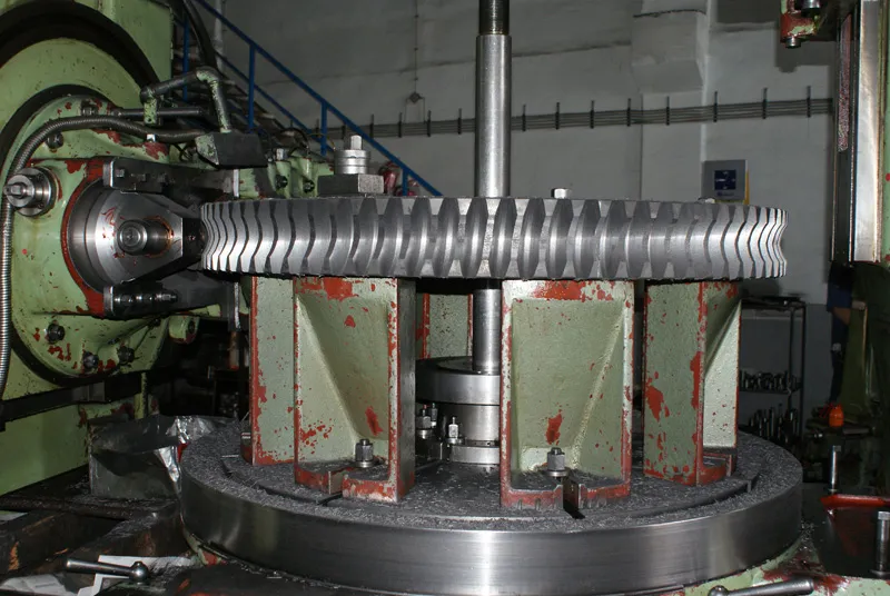
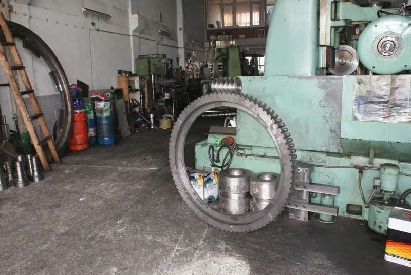
Hobbing, shaping, milling or grinding methods are used.

04 / METHOD

Surface Finishing

Grinding, honing, lapping or shaving improves surface quality.

05 / METHOD

Hardening

Carburizing, nitriding, induction or surface hardening is applied.

06 / METHOD

Inspection & Testing

Dimensional, profile, pitch and runout measurements verify the specification.

TECHNICAL INFO

Worm Gear calculation formulas

Symbol Name Formula Definition
m Normal Module m = 1 / DP A measure of tooth size
α Reference Pressure Angle 20° veya 25° Angle of the tooth profile
Z Number of Teeth tamsayı Number of teeth on the gear
a Center Distance a = (z1 + z2)m / 2 + x1m + x2m Distance between the two shafts
i Speed Ratio i = n1/n2 = z2/z1 Ratio of angular speeds
P Power Transmission P = T × n / 9550 Amount of power transmitted
η Efficiency η = i / (i + f × tan λ) Ratio of output to input power
AREAS OF USE

Worm Gear in which sectors is it used?

Worm gears are widely used in lifting equipment, conveyors, hoists, cranes, ship steering, dividing heads, reducers and automotive lifts, where compact size and high torque are required.
Lifting Equipment
Transport Vehicles
Cranes
Textile Machinery
Ship Steering Mechanisms
Rotary Tables
Dividing Heads
Reduction Gears
Automobiles
Vehicle Lift Shafts
GALLERY

Production samples

RELATED PRODUCTS

Other gear types we manufacture

Worm Gear request a manufacturing quote today.

Contact us via sample or technical drawing, we will provide a custom solution for your needs.

Quick Quote